Delaying a signal by some number of clocks
There can be many reasons for delaying a signal by some number of clocks – it could be to match a pipeline delay, or to form a synchronizer.
In synthesizable Verilog, this would be done by introducing some number of pipeline registers, with each register feeding into the next one.
module dly_test0 (
  input wire clk,
  input wire sig,
  output bit sig_dly
);

bit sig_d1, sig_d2, sig_d3, sig_d4;
always @(posedge clk) begin
  sig_d1 <= sig;
  sig_d2 <= sig_d1;
  sig_d3 <= sig_d2;
  sig_d4 <= sig_d3;
  sig_dly <= sig_d4;
end

endmodule
However in the testbench, we can use SystemVerilog to schedule the signal to change some number of clocks in the future.
Breaking down the below code block, the always block is triggered by the rising edge of clk. On each rising edge, sig_dly will be scheduled to wait for 4 rising clock edges before setting it to the current value of sig (before the 4 clock delay). This is repeated on each rising clock edge, effectively delaying sig by 5 clocks.
module dly_test1 (
  input wire clk,
  input wire sig,
  output reg sig_dly
);

always @(posedge clk)
  sig_dly <= repeat (5-1) @(posedge clk) sig;

endmodule
The neat thing about this is that the amount of delay is configurable – allowing for changing the number of clocks the signal is delayed at each clock edge.
To run this, I wrote a simple testbench that drove the clock, then toggled the input sig every couple of clocks. It then checked that both sig_dly0 and sig_dly behaved the same.
module tb ();

bit clk = 1'b0;
bit sig = 1'b0;
bit sig_dly0, sig_dly1;

always #5 clk <= !clk;

dly_test0 A0 (
  .clk (clk),
  .sig (sig),
  .sig_dly (sig_dly0)
);

dly_test1 A1 (
  .clk (clk),
  .sig (sig),
  .sig_dly (sig_dly1)
);

always @(posedge clk) begin
  #1;
  assert (sig_dly0 == sig_dly1) else
    $error("sig_dly0:%b, sig_dly1:%b", sig_dly0, sig_dly1);
end

initial begin
  $dumpfile("dly.vcd");
  $dumpvars(0, tb);

  repeat(3) @(posedge clk);
  #1; sig = 1'b1;

  repeat(3) @(posedge clk);
  #1; sig = 1'b0;

  repeat(3) @(posedge clk);
  #1; sig = 1'b1;

  repeat(8) @(posedge clk);
  $finish;
end

endmodule
I then created a simple Makefile around Icarus Verilog based off this example.
SRC       = dly.sv dly_test0.sv dly_test1.sv
VCD       = dly.vcd
COUTPUT   = dly

COMPILER  = iverilog
SIMULATOR = vvp
VIEWER    = /Applications/gtkwave.app/Contents/Resources/bin/gtkwave

CFLAGS    = -g2012 -Wall
SFLAGS    =
VFLAGS    = view.gtkw

# Create the VCD
$(VCD) : $(COUTPUT)
	make run

# Create the compiled executable
$(COUTPUT) : $(SRC)
	$(COMPILER) $(CFLAGS) -o $(COUTPUT) $(SRC)

# Simulate the testbench
run : $(COUTPUT)
	$(SIMULATOR) $(SFLAGS) $(COUTPUT)

# View the waveform
view : $(VCD)
	$(VIEWER) $(VCD) $(VFLAGS) &

# Clean any created files
clean :
	@rm -f $(COUTPUT)
	@rm -f $(VCD)
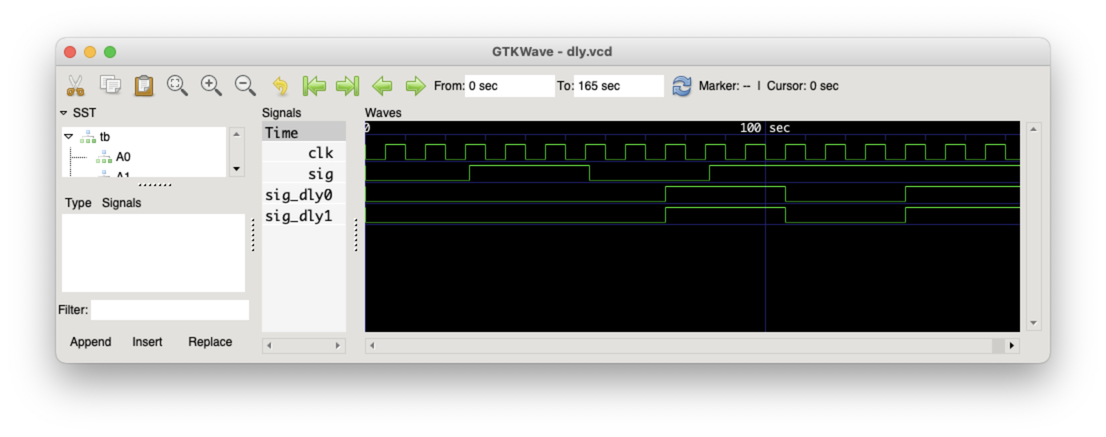
make view compiles the SystemVerilog into an executable, runs the executable, then opens gtkwave to view the waveform.
➜  make view
iverilog -g2012 -Wall -o dly dly.sv dly_test0.sv dly_test1.sv
make run
vvp  dly
VCD info: dumpfile dly.vcd opened for output.
/Applications/gtkwave.app/Contents/Resources/bin/gtkwave dly.vcd view.gtkw &
As can be seen, both methods correctly delayed the input signal by 5 clock cycles.
This post was inspired by the following forum thread.